Browse Items (34 total)
Sort by:
-
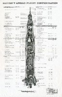
"Saturn V Apollo Flight Configuration."
Drawn by Don Sprague at the Huntsville Engineering section of Boeing. -
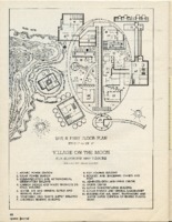
Map of "Village on the Moon for Scientists and Visitors," from Space Journal, vol. 1, no. 4, Fall 1958.
Japanese architect and engineer Hiroshi Kumagai drew this map of a moon base to accompany his article "A Proposal for a Village on the Moon." -
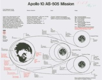
Apollo 10/AS-505 mission chart.
The chart includes diagrams, mission statistics, crew, and notes. There is an additional copy in the David Christensen Collection. -
Various correspondence with David Bowman from 1989 to 1991.
These letters to David Bowman, reporter and editorial writer, all pertain to Bowman's story about Colonel John Nickerson. The first letter includes foot notes and states that he sent a copy of the story to a Washington Post writer. The second letter contains additional information relating to the missile program that may be helpful for the story and a diagram of the original prototype for the Explorer I earth satellite. This set of letters also includes the original letter from David Bowman to Brig. Gen. Harold W. Nelson in which Bowman states he finally photocopied the published transcripts of Colonel Nickerson's court martial. Nelson's reponse follows thanking Bowman for sending the series on Colonel Nickerson. The final letter from Colonel Thomas W. Sweeney includes a working bibliography on the Nickerson case and invites him to visit the Military History Institute. -
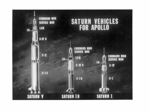
"Saturn vehicles for Apollo photograph."
8 x 10 inch black and white photograph. Contains images of the Saturn V, Saturn IB and Saturn I in reference to one another -
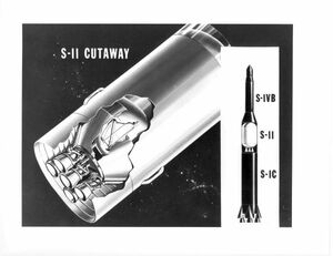
"S-II Engine."
8 x 10 inch black and white diagram of the Saturn II engines. -
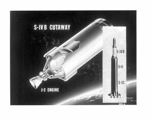
S-IVB cutaway and J-2 engine."
8 x 10 inch black and white diagram of the JII engine and the Saturn IV. -
"S-IC Saturn booster."
8 x 10 inch black and white diagram of the Saturn booster engines. -
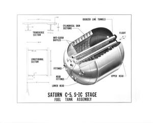
"Saturn C-5, S-IC, stage fuel tank assembly."
8 x 10 inch black and white diagram of a Saturn fuel-tank assembly cross-section. -
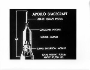
"Apollo spacecraft Diagram."
8 x 10 inch black and white diagram of an Apollo spacecraft, each section labled for easy identification. -
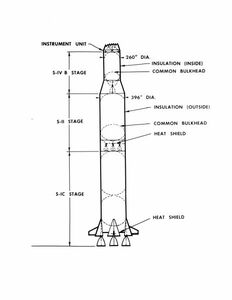
"S-IC stage, S-II stage, S-IVB stage, instrument unit drawing."
8 x 10 inch black and white photograph.; Image includes dimensions and labels of exterior features of the rocket. -
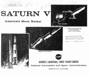
"Saturn V America's moon rocket."
Diagram that displays the Saturn V rocket with a page beneath detailing the function of each stage. -
"Saturn V Apollo flight configuration."
Diagram displaying the internal rooms, pieces and functions of the Saturn V as well as the space-suits of the astronauts. -
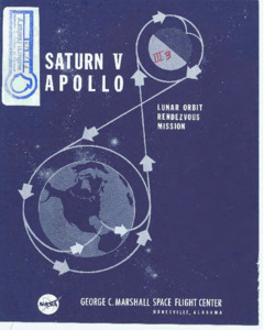
"Saturn V Apollo lunar orbit rendezvous mission."
Diagram explaining the process of a lunar mission from liftoff to recovery. -
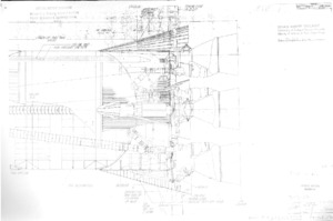
"Saturn V inboard profile : Launch escape system flight separation."
Diagram displaying the launch escape system flight separation in progress. -
"Saturn V service arms : preliminary engineering report."
This report presents the manufacturing requirements for fabricating Saturn V service arms and contains design and operating details of the service arms and associated equipment. Part 1 defines the areas of responsibility necessary for the manufacture of Saturn V service arms and associated equipment. Capability requirements, manufacturing processes, special techniques, schedules, and other areas are detailed in Part 1. The manufacturer selected to fabricate the arms and related equipment must meet the requirements (stated in Part 1. Part 2 contains design and operation details of the service arms, Command Module Access Arm, and related equipment used on or in support of the Launcher-Umbilical Tower for the Saturn V Vehicle at Complex 39. The design and construction of all basic arms is similar. Eight service arms are being designed. The arms are being designed to support all umbilical lines necessary to service the various stages of all Saturn V Vehicles. The arms are also being designed to allow personnel access to the vehicle. Some of the arms must be retracted before vehicle lift-off and others will retract following lift-off. This requirement necessitated the design of umbilical disconnect and arm retract devices which would ensure clearance between the arms and vehicle during lift-off. The Command Module Access Arm is a separate design concept. The arm is used only for astronaut access to the Command Module. Part 2 presents the preliminary design directed toward meeting the requirements stated above. -
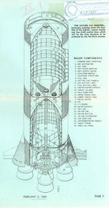
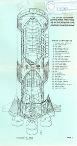
"Saturn S-IC booster : schematic."
This is page 7 of the Marshall Star : Space Information Digest. -
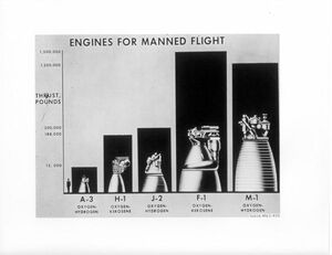
"Engines for Manned Flight."
8 x 10 inch black and white photograph.; Images included are: A-3 oxygen-hydrogen, H-1 oxygen-kerosene, J-2 oxygen-hydrogen, F-1 oxygen-Kerosene, M-1 oxygen-hydrogen. The thrust pounds is also listed.Shows them in reference to a human as a scale. -
"Evolution of Aircraft."
Illustration depicting the history of airplanes across a graph. -
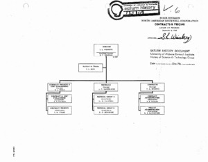
"Contracts & Pricing: Saturn S-II Program".
Indicates the various levels and responsibilities within the Saturn V pricing and contract personnel. September 3, 1968.; Approved S. L. Weinberg. -
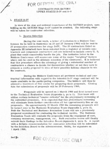
"Contracts for Saturn Upper Stages S-IV and S-V".
Details contracts for upper stages of Saturn IV and Saturn V and includes illustrative appendixes. Archive copy is a photocopy. -
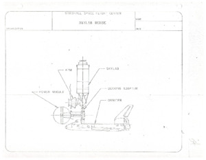
Skylab Reuse Diagrams.
These diagrams depict potential options for reuse of the Skylab habitat for the Space Shuttle program. -
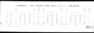
"APOLLO APPLICATION PROGRAM VEHICLES."
This image depicts various Apollo launch vehicles. -
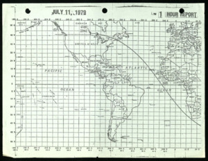
"JULY 11, 1979 1 HOUR REPORT."
This is a report about the Skylab 1 reentry.
