Browse Items (2707 total)
Sort by:
-
Apollo Support Program: Phase 1: Apollo Terminology Standards Final Study Report.
From the abstract: "This report concludes the Phase 1 study activities of the requirements for terminology standardization of the Apollo Integration Support Program. A review is made of the studies conducted and the findings resulting from these activities. Conclusions are drawn and recommendations are made for a proposed Apollo Terminology Handbook. An implementation plan for producing and maintaining an Apollo Terminology Handbook is included. A sample of such a terminology handbook is produced as Part 2 of this report." -
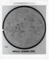
Map of completed and proposed Apollo moon landing sites.
The map shows landing locations on the moon's surface, including proposed landing sites of the cancelled Apollo 18 and Apollo 19 missions. This map was created as part of the Lunar Roving Vehicle (LRV) Project. -
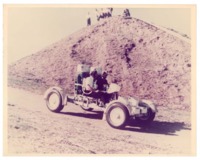
Two astronauts driving a test model of the lunar roving vehicle (LRV).
Developed by Marshall Space Flight Center and built by Boeing, the LRV was an electric vehicle used to explore the Moon's surface during the Apollo 15, 16, and 17 missions. -
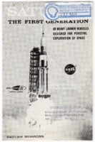
"Saturn I: The First Generation of Heavy Launch Vehicles Designed for Peaceful Exploration of Space."
The leaflet outlines the history of Saturn launches and gives a physical description of the rocket. The description includes a diagram of each stage; specifications of each stage's thrust, propellants, liftoff weight, and burning time; and engine specifications. -
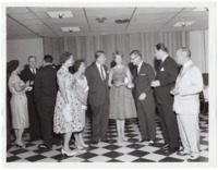
Wernher and Maria von Braun at a cocktail party given for the Alabama legislature.
A note on the back of the photo reads, "Cocktail Party for legislature at time Huntsville wanted Research Park & Institute for university." From left to right: Mrs. Foster Haley, Mrs. Milton Cummings, Wernher von Braun, Maria von Braun, Roscoe Roberts, Ryan DeGraffenried, and Milton Cummings. -
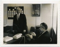
William A. Schulze and Hans Palaoro at Marshall Space Flight Center.
The bulletin board behind Schulze reads "Vehicle Engineering Branch." Palaoro was the head of the Vehicle Systems Engineering Branch of the Structures and Mechanics Division at Marshall Space Flight Center. -
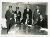
The Apollo Lunar Surface Drill team at Marshall Space Flight Center.
John Bensko, Jr. is seated in the center of the front row. -
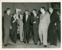
President John F. Kennedy visits Marshall Space Flight Center.
Shown in the photograph, left to right: President John F. Kennedy, Robert C. Seamans, Wernher von Braun, James E. Webb, Vice President Lyndon B. Johnson, Robert S. McNamara, Jerome D. Wiesner, and Harold Brown. -
President John F. Kennedy being interviewed by a reporter while MSFC director Wernher von Braun looks on.
Kennedy visited Huntsville for a second time on Armed Forces Day 1963. His first visit occurred on September 11, 1962. -
Program from "Life in the Universe," the Sixth Annual Von Braun Exploration Forum.
The program includes biographic sketches of the Forum speakers, as well as songs performed by guest speaker and space enthusiast John Denver. -
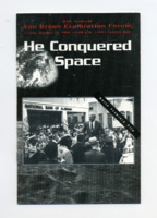
Program from "He Conquered Space," the Ninth Annual Von Braun Exploration Forum.
The program includes biographical sketches of the speakers, including John S. Hendricks, Rick Chappell, and Walter Cronkite. -
"Living in Huntsville and Madison County: Home of George C. Marshall Space Flight Center."
This pamphlet includes a memo to "Key MSFC Employees" from M. Keith Wible, Chief of the Manpower Utilization and Administration Office at Marshall Space Flight Center. -
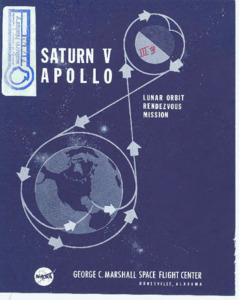
"Saturn V Apollo lunar orbit rendezvous mission."
Diagram explaining the process of a lunar mission from liftoff to recovery. -
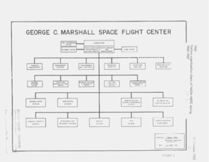
Various organization charts of NASA-MSFC during 1960-1969.
A collection of organization charts from years 1960 to 1969. -
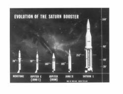
"Evolution of the Saturn Booster."
8 x 10 inch Black & White photograph. MS-G 103-63 Nov. 22, 63 is on the photograph. Displays the evolution of space-rocket designs side-by-side. -
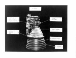
F-1 engine photograph.
8 x 10 inch black and white photograph. Engine parts are labeled. -
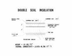
Double seal insulation [drawing] photograph.
8 x 10 inch black and white photograph.; Drawing contains information about the modified epoxy adhesive, aluminum film, mylar film, perforated phenolic honeycomb core, tank skin, mylar honeycomb core, polyurethane adhesive, weight and thermal conductivity.; Photo negative no. 651746 M-268. -
"Conditions contributing to stress corrosion [list] photograph."
8 x 10 inch black and white photograph. A photograph of a list of things contributing to stress corrosion. Referenced by "Materials in Space Exploration." Is part of envelope containing photos accompanying C. E. Cataldo paper "Materials in Space Exploration." -
"Apollo Program Management Volume 3."
According to the introduction found on page ii, this document was created to detail the "MSFC segment of the total Apollo Management process and to describe the methodologies and techniques currently being implemented." -
"AS-203 Technical Information Summary."
"This report outlines, through a series of sketches with accompanying text, the general features of the SA-203 Launch Vehicle and information on launch preparation, the launch facility and mission peculiar experiments." -
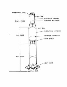
"S-IC stage, S-II stage, S-IVB stage, instrument unit drawing."
8 x 10 inch black and white photograph.; Image includes dimensions and labels of exterior features of the rocket. -
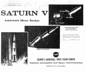
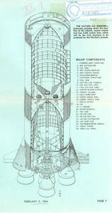
"Saturn V America's moon rocket."
Diagram that displays the Saturn V rocket with a page beneath detailing the function of each stage. -
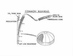
"Common bulkhead drawing."
8 x 10 inch black and white photograph; This is a cutaway drawing of the bulkhead with information about the LH2 tank skin, insulation, Aft LOX bulkhead, 2014-T6 alum skin and fiberglass core. Part of an envelope with photos accompanying C. E. Cataldo paper "Materials in Space Exploration." -
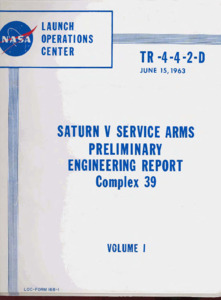
"Saturn V service arms : preliminary engineering report."
This report presents the manufacturing requirements for fabricating Saturn V service arms and contains design and operating details of the service arms and associated equipment. Part 1 defines the areas of responsibility necessary for the manufacture of Saturn V service arms and associated equipment. Capability requirements, manufacturing processes, special techniques, schedules, and other areas are detailed in Part 1. The manufacturer selected to fabricate the arms and related equipment must meet the requirements (stated in Part 1. Part 2 contains design and operation details of the service arms, Command Module Access Arm, and related equipment used on or in support of the Launcher-Umbilical Tower for the Saturn V Vehicle at Complex 39. The design and construction of all basic arms is similar. Eight service arms are being designed. The arms are being designed to support all umbilical lines necessary to service the various stages of all Saturn V Vehicles. The arms are also being designed to allow personnel access to the vehicle. Some of the arms must be retracted before vehicle lift-off and others will retract following lift-off. This requirement necessitated the design of umbilical disconnect and arm retract devices which would ensure clearance between the arms and vehicle during lift-off. The Command Module Access Arm is a separate design concept. The arm is used only for astronaut access to the Command Module. Part 2 presents the preliminary design directed toward meeting the requirements stated above. -
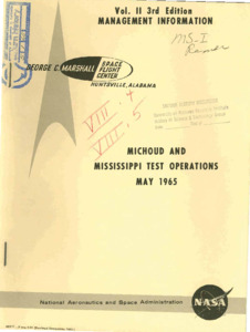
"Michoud and Mississippi test operations : May 1965."
This document contains copies of management charts and photographs maintained in the Management Information Office of the Executive Staff on Michoud and Mississippi Test Operations. Information on other MSFC activities and facilities will be published in separate volumes as indicated on the following page. Most of these charges are included in Dr. von Braun's, Dr. Rees' and Mr. Gorman's Management Information Consoles. -
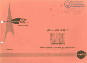
Visual aids library slide guide.
This document includes revisions. There are missing pages from page 237-238. This reference document catalogues all MSFC oriented visual aids filed in the Visual Aids Library of Marshall Space Flight Center. These visual aids are updated by the Graphic Engineering & Models Branch, Industrial Operations Program Management Information Office, and the Research and Development Operations Management Office. The purpose of the Visual Aids Library is to provide management data visuals in the form of slides (3 X 4 and 2 X 2), or black and white prints, to MSFC offices and laboratories, and other centers, who have a valid requirement. The visual aids are issued on a loan basis in order to obtain as wide a use for each visual and to assure that the latest revisions are incorporated in the issued item. Visuals may be ordered from the Visual Aids Library, located on the 10th floor of building 4200 (Phone 876-7237, 876-6960, 876-0983). In addition to the visuals published in this book, photographs from prime contractors are available from Industrial Operations, Program Management Information Office, Room 621, building 4201. Visuals with erroneous or obsolete information should be brought to the attention of the Visual Aids Library, preferably in writing, so that corrections can be made immediately. This publication will be kept current through distribution of pages of new visuals and notification will be made on obsolete visuals so they may be crossed out in the catalogue. Comments and suggestions concerning this publication will be greatly appreciated. Changes in the distribution lists should be directed to Mr. Gordon 0. Willhite, or Mrs. Opal Tabor, Visual Aids Library, MS-G. -
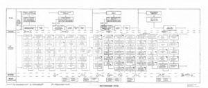
"Management system"
The title has been cut off of document. This was placed inside the document Configuration Management. An organizational chart of plans and critical events related to those plans. -
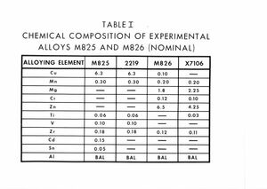
"Table I : chemical composition of experimental alloys."
8 x 10 inch black and white photograph of a table reperesenting the chemical composition of alloys M825 and M826. -
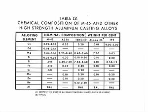
"Table IV : chemical composition of M-45 and other high strength aluminum casting alloys."
8 x 10 inch black and white photograph of a graph displaying different alloys and comparing their 'nominal composition weight per cent' to one another. -
"M-45 casting alloy : Gyro stabilizer support."
8 x 10 inch black and white photograph of a gyro stabilizing support. -
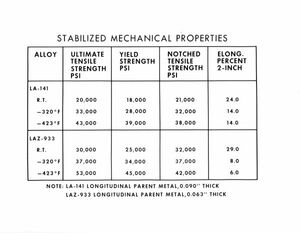
"Stabilized mechanical properties [table] photograph.
8 x 10 inch black and white photograph including a table that displays the stabilized mechanical properties of the following alloys: :LA-141 and LAX-933. -
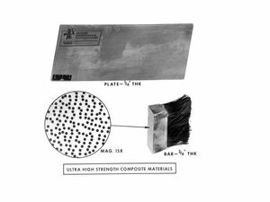
"Ultra high strength composite materials."
8 x 10 inch black and white photograph which displays an image that includes the plate, bar and the magnification of the bar to display its molecules. -
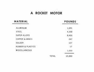
"Rocket motor" material list photograph.
8 x 10 inch black and white photograph of a rocket motor material list. The weight of the material is measured in pounds. -
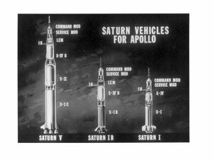
"Saturn vehicles for Apollo photograph."
8 x 10 inch black and white photograph. Contains images of the Saturn V, Saturn IB and Saturn I in reference to one another -
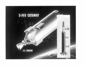
S-IVB cutaway and J-2 engine."
8 x 10 inch black and white diagram of the JII engine and the Saturn IV. -
"S-IC Saturn booster."
8 x 10 inch black and white diagram of the Saturn booster engines. -
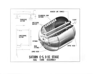
"Saturn C-5, S-IC, stage fuel tank assembly."
8 x 10 inch black and white diagram of a Saturn fuel-tank assembly cross-section. -
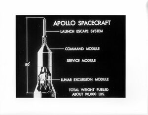
"Apollo spacecraft Diagram."
8 x 10 inch black and white diagram of an Apollo spacecraft, each section labled for easy identification. -
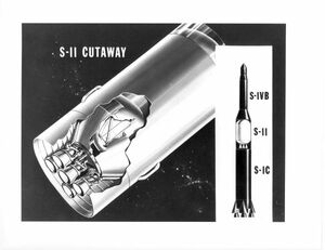
"S-II Engine."
8 x 10 inch black and white diagram of the Saturn II engines. -
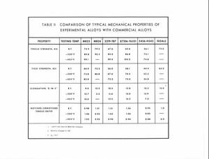
"Table II : comparison of typical mechanical properties of experimental alloys with commercial alloys."
8 x 10 inch black and white photograph of a table comparing the tensile strength of each alloy in relation to a desired goal.
