Browse Items (8 total)
Sort by:
-
"A Hybrid Simulation for Dynamic Verification of Saturn Guidance and Control Subsystems."
This paper presents a discussion of a hybrid simulation used to dynamically verify the Saturn Guidance and Control subsystems. First, the Saturn vehicle is briefly described to provide background information. The Instrument Unit (IU) is considered in more detail to give a proper setting for the Guidance and Flight Control (G and FC) discussion that follows. After a brief description of the actual G and FC System operation, simulation models of the G and FC components are considered in detail. This is followed by a discussion of the model assignment to a particular computer (digital or analog) and justification for making that assignment. Finally, results of the AS-204/LM1 hybrid simulation studies are briefly considered with mention of the actual flight data. -
"A Practical Approach to the Optimization of the Saturn V Space Vehicle Control System Under Aerodynamic Loads."
This paper includes the equations for the bending moment of a launch vehicle with the effects of bending and sloshing dynamics. It also includes a comparison between the bending moment response envelope of the measure winds and the bending moment response of the MSFC synthetic wind profile. -
"Crew Briefing : Instrument Unit Stage Presentation".
Document outlining different slides of a presentation containing numerous organizational charts, diagrams and bullet-list points. -
"Saturn IB/V instrument unit."
This brochure provides some basic, general information about the lnstrument Unit, a very important part of the Saturn IB and Saturn V launch vehicles. These launch vehicles are being developed primarily for the Apollo program for manned lunar exploration but will also be used for future space missions. -
"Guidance and Control of Saturn Launch Vehicles."
The navigation, guidance, and control modes and problems of the Saturn launch vehicles are given as the requirements for the guidance and control methods. Two path adaptive guidance modes, featuring flight path optimization, in the form of a polynomial mode and an iterative mode are given in their computation form and compared with respect to mission flexibility, implementation requirements, and performance. Attitude control during the propelled flight phases requires consideration of various bending and sloshing modes; stability of the control system is obtained by phase stabilization of the low frequencies and by attenuation of the higher frequencies. Typical shaping networks and their transfer functions are given. The attitude control system during coasting periods is briefly described. The functional behavior and characteristic data of the main guidance and control hardware such as the inertial sensors, stabilized platform, digital computer, data adapter, control computer, and actuation system are described. Reliability requirements are emphasized. The principle of redundancy is extensively used to obtain highest reliability for long operating times. Data and results from recent Saturn I flights summarize the performance of the guidance schemes. -
"Crew Briefing : Instrument Unit Stage Presentation".
Document outlining different slides of a presentation containing numerous organizational charts, diagrams and bullet-list points. -
"A comparison of four control systems proposed for Saturn V launch vehicles."
Presented are the results of a study comparing four proposed control systems for the first stage flight of Saturn V launch vehicles. The primary basis of comparison is the effect on structural loads, using the bending moments at three stations as load indicators. Two of the systems sense only the vehicle attitude and attitude rate, while the other two systems also sense the lateral acceleration. A yaw plane wind response analysis, including rigid body translation, rigid body rotation, four bending modes, five slosh modes, and a non ideal control system, was performed. The winds used in the study were the Marshall synthetic profile and three selected Jimsphere-measured real wind profiles. Load relief obtained from the addition of accelerometer feedback in the control loop amounted to about 10 percent at maximum bending moment station. In view of predicted structural capabilities of the vehicle, this reduction in loads was not considered sufficient to offset the added complexity and the slight reduction in rigid body stability . -
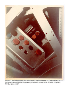
Internal Views of Skylab Control Systems, External and Internal views of Skylab Electronic Systems.
The images depict in internal view of the Skylab control systems. The images depict the control systems for the Skylab airlock The images depict internal and external views of Skylab electronic systems.
