Browse Items (47 total)
Sort by:
-
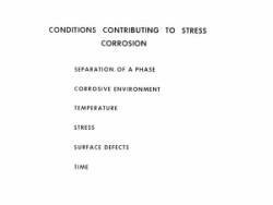
"Conditions contributing to stress corrosion [list] photograph."
8 x 10 inch black and white photograph. A photograph of a list of things contributing to stress corrosion. Referenced by "Materials in Space Exploration." Is part of envelope containing photos accompanying C. E. Cataldo paper "Materials in Space Exploration." -
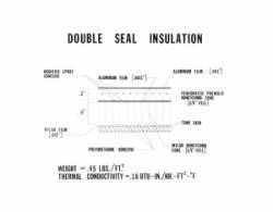
Double seal insulation [drawing] photograph.
8 x 10 inch black and white photograph.; Drawing contains information about the modified epoxy adhesive, aluminum film, mylar film, perforated phenolic honeycomb core, tank skin, mylar honeycomb core, polyurethane adhesive, weight and thermal conductivity.; Photo negative no. 651746 M-268. -
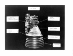
F-1 engine photograph.
8 x 10 inch black and white photograph. Engine parts are labeled. -
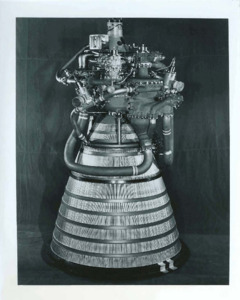
"Pratt & Whitney Aircraft RL10 liquid hydrogen rocket engine"
Photograph of a Pratt & Whitney rocket engine. -
"The Common Bulkhead for the Saturn S-II Vehicle: Unique Manufacturing Effort Adds to Space-Age Hardware Technology".
Presentation regarding the construction of Apollo and Saturn rockets. -
Combustion Oscillations in F-1 Engine.
The set of documents includes an introductory letter written by D. Brainerd Holmes and Tischler's report with the subject "F-1 Combustion Instability Report for Associate Administrator; Period March-April, 1963". -
"Development of the Saturn S-IV and S-IVB Liquid Hydrogen Tank Internal Insulation."
In April of 1960 the Douglas Aircraft Company was awarded a contract to develop the second and uppermost stage for the Saturn I space booster. In order to realize the high specific impulse available, this stage, called the S-IV, was to utilize liquid hydrogen and liquid oxygen as the propellants. After burn-out of the first stage, the S-IV Stage was to ignite its engines at an altitude of approximately 200,000 feet, burn for approximately 8 minutes, and inject a 20,000 lb spacecraft into a low earth orbit. This program represented Douglas's first major endeavor with liquid hydrogen. It was necessary to develop an insulation for the S-IV Stage that was capable of withstanding the thermal shock associated with loading, could provide adequate insulative properties to limit the flow of heat into the hydrogen, and was of minimum weight. This latter fact cannot be over emphasized because every extra pound of insulation is one less pound of available payload weight. -
Development of LOX/RP-1 engines for Saturn/Apollo launch vehicles.
The development of liquid rocket engines follow similar patterns regardless of engine size. During the development of the H-1 and F-1 engines, may problems were encountered. Mehtods of solving the combustion instability problem are discussed.; AIAA 4th Propulsion Joint Specialist Conference, Cleveland, Ohio, June 10-14, 1968.; Also available on NASA Technical Reports Server (NTRS) as unclassified. Can be ordered. Also on AIAA. -
"Development of LOX/RP-1 Engines for Saturn/Apollo Launch Vehicles."
The development of liquid rocket engines follow similar patterns regardless of engine size. During the development of the H-1 and F-1 engines, many problems were encountered. Methods of solving the combustion instability problem are discussed. A description is given of the major components of each engine, outlining their unique features. The requirements for an insulation cocoon are discussed. Problems associated with materials substitution are provided; also highlighted is the fact that problems occur after engine deliveries and require continued development support. Safety features incorporated on the engines are mentioned. Solution to problems encountered in flight are discussed. Upratings of both engines systems are presented graphically.; On the NASA Technical Reports Server (NTRS) unclassified. Can also be found on AIAA. -
"Development of LOX-Hydrogen Engines for the Saturn Apollo Launch Vehicles."
During the development of the RL-10 and J-2 engines, many problems were encountered. Solutions to the significant problems are contained. A description of these LOX-Hydrogen engines, outlining the unique features of each will be given. Performance parameters for both engine systems are tabulated. Specific applications to various stages are shown. -
"Design of the Saturn S-IV Stage Propellant Utilization System."
Describes the SIV vehicle and its components. Presented at: IRE International Convention. -
"Design and Development of a 1,500,000-Pound-Thrust Space Booster Engine."
Describes the F-1 engine design and components. -
"Failure Investigations of Large Liquid Propelled Rocket Engine Components."
Case histories of seven typical failures in large liquid propelled rocket engines components have been prepared. Quite simple to complex investigations are presented covering a variety of failure modes in a variety of materials. Included are successful solutions to the failure problems investigated.; Archive copy is a poor photocopy. -
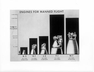
"Engines for Manned Flight."
8 x 10 inch black and white photograph.; Images included are: A-3 oxygen-hydrogen, H-1 oxygen-kerosene, J-2 oxygen-hydrogen, F-1 oxygen-Kerosene, M-1 oxygen-hydrogen. The thrust pounds is also listed.Shows them in reference to a human as a scale. -
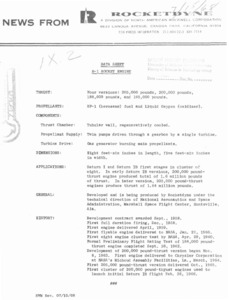
"Data Sheet: H-1 Rocket Engine."
News from Rocketdyne. -
"Information About Pratt & Whitney Aircraft Florida Research and Development Center."
A history of Pratt and Whitney Aircraft Florida Research and Development Center. -
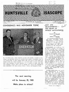
Huntsville Isascope: Volume V, No. 9.
The following article is a digest from the Book, "From Peenemunde to Outer Space", commemorating the fiftieth birthday of Wernher von Braun, March 23, 1962 condensed by H. M. Hammac). -
"Launch Vehicle Engines Project Development Plan."
The primary mission objective of the 5-2 Engine Project is to continue development of a liquid oxygen/liquid hydrogen engine. capable of high-altitude restart. Both Saturn IB and Saturn V vehicles will use the J-2 engine; the S-IVB stage of Saturn IB vehicles and S-IVB stage of Saturn V vehicles will be equipped with a single J-2 engine. The S-I1 stage of Saturn V vehicles will use a cluster of five J-2 engines. Figure 1-3 illustrates these stages. -
"Launch Information: Saturn S-IV and the RL10 Engine."
The RL10, which powers the National Aeronautics and Space Administration' s Saturn S-IV, is the newest propulsion system to be put to work in advancing our nation's space effortr On November 27, 1963, a pair of RLlO's successfully powered a five-ton Centaur space vehicle in earth orbit in the first flight demonstration of the outer space powerplant which uses high-nenergy liquid hydrogen as fuel. A six-engine cluster of RLlO' s, generating a total of 90, 000 pounds of thrust, powers the Saturn S-IV stage. The 15, 000 pound-thrust engine was designed and developed for NASA's Mar shall Space Flight Center at Pratt & Whitney Aircraft's Florida Research and Development Center, 20 miles northwest of West Palm Beach. -
"Data Sheet J-2 Rocket Engine."
A datasheet describing the function of the J-2 rocket engine. -
"List of Equipment, Components, Materials, and/or Services Now Being Developed, Fabricated or Performed."
Lists of different parts of rockets. -
"Liquid Rocket Propellant Compatibility Testing."
Material-propellant compatibility as related to liquid rocket propulsion system design criteria is discussed and applicable test methods to derive usable design data are presented. Test methods, with emphasis on metallic materials, are discussed and the shortcomings of a number of these test methods are pointed out. These tests include static immersion tests, stress-corrosion tests, flow tests, impact tests, and tests to determine the effect of cracks and notches in metals on compatibility. A general outline for the evaluation of metallic and nonmetallic materials with respect to propellant compatibility is presented. -
"Liquid Rocket Engines."
This paper presents a discussion on liquid propellant rocket engines. The first part contains a discussion on liquid propellants, including a description of various propellant types such as cryogenic, storable,bipropellant, and monopropellant. This part also points out desirable physical properties and includes a section on performance outlining the methods by which performance is calculated and shows performance for various liquid rocket propellant combinations. -
"Liquid Hydrogen Technology, J-2 Engine."
subject of the speech is the application of oxygen/hydrogen technology the 5-2 engine system. -
"Liquid Rockets."
This review indicates recent developments which have occurred in the liquid rocket engine field, special development areas associated with the liquid engines in current usage, and several trends which may be expected in the design of future advanced rocket engines. -
"Materials in space exploration."
This paper presents a general review of major structural alloys that have been used in liquid rockets and space vehicles, the current state-of-the-art as applied to the Apollo launch vehicle systems, and discusses some materials currently under development for future requirements in vehicles for space exploration. Some aspects of the importance of corrosion resistant materials and suitable protective measures are discussed, as applied to both flight hardware and associated ground support equipment. -
"Manned space flight schedules. Vol. III, launch vehicles : book 4, engines."
OMSF Program Status Review October 1965.; Edition "A" -
"Next stop : the moon."
Release describing the launch of the Apollo 11. -
"Problems in cryogenic pump design for space application."
Report detailing the problems surrounding cryogenic pump design for space travel and missions. -
"Recent NASA experience with hydrogen engines."
This paper presents a review of the experience which has accumulated in the development of the Liquid Hydrogen J-2 and RL10 rocket engines. These engines are being developed by the Rocketdyne Division of North American Aviation and Pratt & Whitney Aircraft, a Division of United Aircraft Corporation respectively.; On NASA Technical Reports Server (NTRS) as Unclassified; No Copyright; Unlimited; Publicly available. Also found on AIAA site. -
"Propulsion lecture."
Lecture discussing the types of propellant used in space rockets. -
"Rocket engine turbo pumps for space travel."
Finding the turbopump arrangement which is best suited for a given rocket engine - space travel applications - constitutes an important task. The arrangement depends upon a large variety of different factors, such as, the engine cycle, weight, the liquids to be pumped, the cavitation performance, the bearings and their lubrication, the seals and the turbine. In this report these factors and their influence on the turbopump configuration are discussed. It is shown that three of them: weight, propellants to be pumped and obtainable suction performance have the largest influence on the selection of the turbopump. A systematic approach is outlines for the design process, which allows to arrive at a turbopump arrangement best suited for a given application. -
"Rocket engine selection criteria."
This paper considers many of the factors and criteria which have to be considered and evaluated when selecting a specific rocket engine for a given vehicle application. The lists of criteria can be helpful as checklists in design and systems engineering of a rocket propulsion device. About ten different applications are examined to illustrate the relative importance of some of these selection criteria. There will be groupings of our major types of criteria; namely, performance, operational, economic and so-called judgment criteria. In many cases the last three categories are equally or more important than the performance criteria in selecting one of several rocket engines for a specific application. The actual selection usually is a compromise to make the rocket engine responsive to several important criteria. -
"Reliability and quality management."
The role of Reliability and Quality in NASA program management is well defined by the NPC 200 series and complimentary procurement regulations. -
"Saturn S-IV cryogenic weigh system. Part I : propellant utilization."
In order to achieve maximum vehicle efficiency, it is essential that the vehicle propellants be loaded to desired values and that these propellants approach simultaneous depletion at the end of powered flight. To accomplish precise loading and assure minimum residuals, a highly accurate and repeatable, vehicle located, propellant management (PM) or propellant utilization (PU) system must be used. As the ability to load propellants to predetermined values depends directly on the ability of the system to accurately sense the propellant masses, it is essential that the system be calibrated with respect to propellant mass under conditions resembling those to be experienced during final loading and powered flight. The use of a cryogenic weight system will reduce the unknown factors in capacitance sensor element shaping, tank geometry, and propellant properties to a degree which will permit the determination of propellant masses to with .025%. -
"Saturn S-IV cryogenic weigh system. Part IV : safety."
During cryogenic weigh system operation, hydrogen when combined with oxygen can create an unsafe condition. Therefore the concentration of the residual oxygen and hydrogen from leaks in the cryogenic weigh environmental bags must be known at all times during the cryogenic weigh. Hydrogen and oxygen detectors will provide the optimum method for maintaining safe conditions. Hydrogen properties and safe mixtures are reviewed. The method selected to analyze the oxygen content is discussed. The selection, development, and testing of a hydrogen detector system is examined. -
"S-IVB Saturn high energy upper stage and its development."
The development of carrier rockets For manned space missions has been one of the major activities in the aerospace field during the past decade. The early space efforts were made possible by the existence of large ballistics missiles. It soon became obvious that the delivery of weapons and the launch of large spacecraft could not be combined into one operational system in an efficient way; therefore, a family of spacecraft boosters had to be created. -
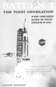
"Saturn I : the first generation of heavy launch vehicles designed for peaceful exploration of space."
A basic description of the Saturn rockets alongside diagrams for context. -
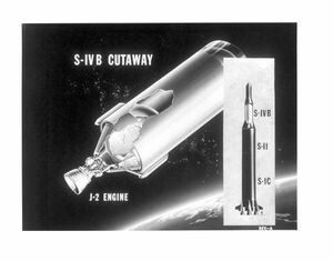
S-IVB cutaway and J-2 engine."
8 x 10 inch black and white diagram of the JII engine and the Saturn IV.
